
Every concrete structure moves. It shrinks as it cures, expands and contracts with temperature, and settles slightly under load. Left uncontrolled, that movement produces random cracking — unsightly, structurally unpredictable, and difficult to repair. Construction joints in concrete solve this problem by creating planned discontinuities: deliberate breaks in the concrete mass that control where movement occurs, accommodate thermal expansion, and separate elements that would otherwise restrain each other.
The types of construction joints in concrete are not interchangeable. Each joint type serves a specific function — controlling shrinkage, accommodating expansion, isolating adjacent elements, or connecting sequential pours. Using the wrong joint type, placing it incorrectly, or spacing it too far apart produces the same result as having no joint at all: uncontrolled cracking in the wrong places.
This guide covers every joint type used in residential and structural concrete — design rules, spacing requirements, depth specifications, materials, and the most common placement mistakes — so you can specify and install joints that actually work.
If cracking has already occurred in your concrete because joints were omitted or incorrectly placed, our guide on types of concrete damage covers assessment and repair options for the resulting deterioration.
For concrete volume calculations before any new pour, use the concrete calculator at ConcreteCal.
Table of Contents
- What Are Construction Joints in Concrete and Why Do They Matter?
- Main Types of Construction Joints in Concrete
- Control Joints — Managing Shrinkage Cracking
- Expansion Joints — Accommodating Thermal Movement
- Isolation Joints — Separating Independent Elements
- Construction Joints — Cold Pour Connections
- Contraction Joints in Slabs on Grade
- Joint Design by Project Type
- Common Joint Design Mistakes to Avoid
- Frequently Asked Questions
What Are Construction Joints in Concrete and Why Do They Matter?
A construction joint is any planned break or discontinuity intentionally introduced into a concrete element — as opposed to an unplanned crack, which forms where stress exceeds the concrete’s tensile capacity.
Joints matter because concrete is a restrained material. A slab cannot shrink freely — subgrade friction, adjacent structures, and embedded reinforcement all resist movement. When concrete tries to shrink and cannot, tensile stress builds. Without joints creating planned weak points, that stress finds its own release: random cracks across the slab surface, at re-entrant corners, or at the worst possible structural location.
Construction joints are an essential part of concrete construction because they help maintain structural integrity while allowing work to continue in planned stages. Choosing the correct joint type improves durability, minimizes the risk of uncontrolled cracking, and ensures long-term performance for slabs, walls, foundations, and other concrete structures. The American Concrete Institute recommends a minimum 6-inch slab at 3,500 PSI for vehicle lifts, and many lift manufacturers specify a 4,000 PSI minimum with rebar before installation.
Properly designed and placed joints redirect that inevitable movement to controlled, predictable locations — straight lines where the joint material can accommodate the movement rather than ragged cracks that admit water and deteriorate progressively.
Joints vs. Cracks — The Key Difference
| Planned Joint | Unplanned Crack | |
|---|---|---|
| Location | Designed, predictable | Random, unpredictable |
| Appearance | Straight, clean | Irregular, ragged |
| Water resistance | Sealed, protected | Open, unprotected |
| Structural impact | Controlled, designed | Unknown, potentially serious |
| Repair requirement | Routine maintenance | Assessment + repair |
| Cost | Low — designed in | High — reactive fix |
The goal of joint design is to ensure that all movement in the concrete occurs at joints — not at cracks. When this is achieved, the concrete performs as designed, waterproofing is maintained, and maintenance is predictable.
How Joints Control Concrete Movement
Concrete movement comes from three sources:
Shrinkage — volume reduction as water evaporates during curing. A 100-foot concrete slab can shrink by 0.5–0.75 inches during curing — generating enormous tensile stress if restrained.
Thermal movement — expansion and contraction with temperature change. Concrete expands approximately 0.000006 inches per inch per °F. A 100-foot slab experiences a 0.72-inch length change between 0°F and 120°F (a realistic extreme range in many US climates).
Structural movement — deflection under load, settlement, and creep (long-term deformation under sustained stress).
Different joint types address different movement sources — which is why using only one joint type throughout a structure is rarely adequate.
Main Types of Construction Joints in Concrete
| Joint Type | Primary Function | Movement Accommodated | Typical Location |
|---|---|---|---|
| Control joint | Direct shrinkage cracking | Contraction only | Slab field, pavement |
| Expansion joint | Accommodate thermal expansion | Expansion + contraction | Fixed boundaries, long runs |
| Isolation joint | Separate independent elements | All movement types | Slab-to-wall, slab-to-column |
| Construction joint | Connect sequential pours | None (load transfer) | Pour boundaries |
| Contraction joint | Induce controlled cracking | Contraction | Slabs on grade |
Note that control joints and contraction joints are functionally similar — both induce planned cracking at a weakened section. The distinction is primarily in how they’re formed: control joints are cut or tooled grooves; contraction joints are a broader category that includes all methods of inducing planned contraction cracking.
Control Joints — Managing Shrinkage Cracking
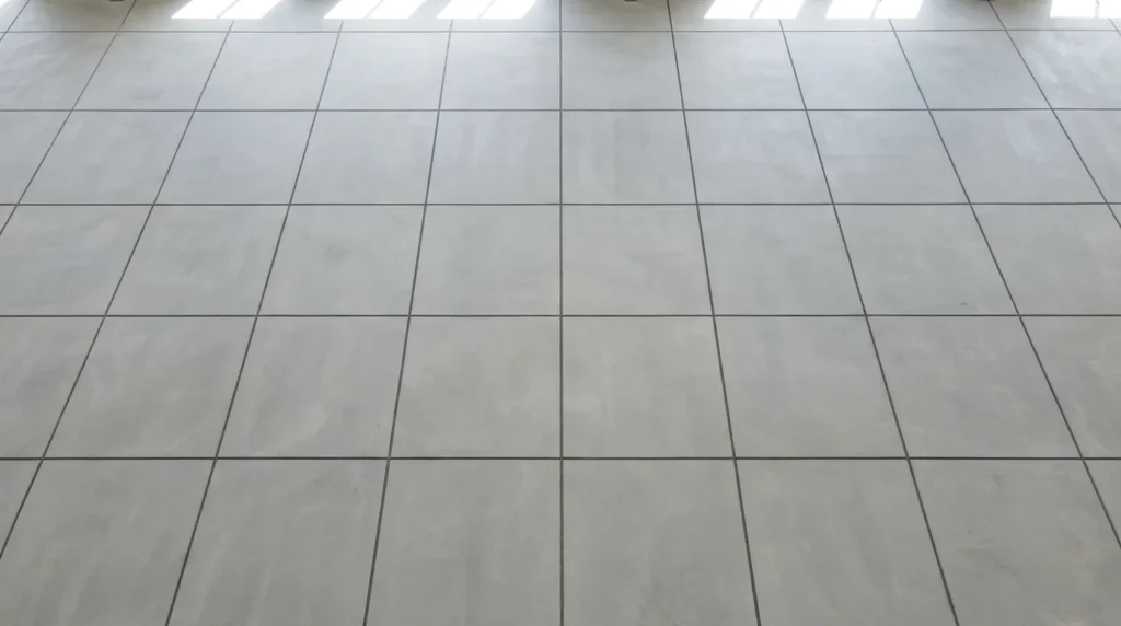
Control joints are the most common joint type in residential and commercial flatwork. They are grooves cut or tooled into the concrete surface — creating a plane of weakness where shrinkage cracking is directed and controlled.
The joint does not prevent cracking. It ensures that when the slab cracks — and it will — the crack occurs at the joint, in a straight line, at a predictable location where it can be sealed and maintained.
Saw-Cut Control Joints
Saw-cut joints are made with a concrete saw after the concrete has hardened sufficiently to resist raveling at the cut edges — typically 4–12 hours after finishing, depending on concrete mix, temperature, and set time.
Timing is critical: Cut too early and the saw tears the aggregate rather than cutting cleanly. Cut too late and the slab has already cracked randomly before the joint was installed.
Early-entry dry-cut saws can cut within 1–4 hours of finishing — significantly reducing the risk of uncontrolled cracking before joints are established. These are the standard tool on commercial flatwork where large slab areas must be jointed quickly.
Worked Example: A 10,000 sq ft warehouse floor poured in sections. Concrete placed at 7:00 AM, finished by 10:00 AM. Early-entry saw begins cutting control joints at 11:30 AM — 1.5 hours after finishing. All joints cut by 2:00 PM. Without early-entry capability, the first random shrinkage cracks would appear by 3:00–4:00 PM before conventional saws could begin cutting.
Tooled Control Joints
Tooled joints are formed in fresh concrete using a grooving tool — a hand tool or walk-behind groover that cuts a groove into the surface while the concrete is still plastic.
Advantage: No timing risk — formed before the concrete sets Limitation: Tooled grooves are typically shallower than saw cuts and may not provide adequate depth for crack control in thicker slabs
Tooled joints are the standard approach for residential flatwork — patios, driveways, sidewalks — where the contractor forms joints immediately after finishing rather than returning with a saw.
Control Joint Spacing Rules
Joint spacing determines whether the joints actually control cracking or whether the slab cracks between them.
Standard residential rule:
Joint spacing (feet) = 2–3 × slab thickness (inches)
| Slab Thickness | Maximum Joint Spacing |
|---|---|
| 3.5 inches | 7–10 feet |
| 4 inches | 8–12 feet |
| 5 inches | 10–15 feet |
| 6 inches | 12–18 feet |
For high-shrinkage conditions (hot weather, low humidity, high water-cement ratio), use the lower end of the range. For well-controlled mixes with low water-cement ratio and fiber reinforcement, the upper end is acceptable.
Panel shape rule: Joint panels should be as square as possible — length-to-width ratio not exceeding 1.5:1. Long, narrow panels are more prone to diagonal cracking between joints.
Control Joint Depth Requirements
A control joint must be deep enough to create a genuine plane of weakness — otherwise the slab cracks at full depth wherever it wants rather than at the joint.
Minimum depth: One-quarter of the slab thickness
| Slab Thickness | Minimum Joint Depth |
|---|---|
| 4 inches | 1 inch |
| 5 inches | 1.25 inches |
| 6 inches | 1.5 inches |
| 8 inches | 2 inches |
Joints shallower than one-quarter depth frequently fail to control cracking — the slab cracks at full depth adjacent to the shallow groove rather than at the joint.
Expansion Joints — Accommodating Thermal Movement
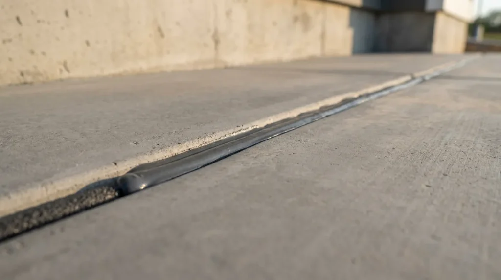
Expansion joints are full-depth breaks in the concrete filled with compressible material — they allow the concrete to expand freely without generating restraint stress against adjacent structures.
Unlike control joints (which only accommodate contraction), expansion joints must accommodate both expansion and contraction — the filler material compresses when the concrete expands and recovers when it contracts.
Expansion Joint Materials and Fillers
| Material | Compressibility | Recovery | Durability | Best Use |
|---|---|---|---|---|
| Premolded fiber board | Good | Fair | Good | General flatwork |
| Closed-cell foam | Excellent | Excellent | Good | Residential slabs |
| Neoprene | Excellent | Excellent | Very good | Pavement, bridges |
| Cork | Good | Fair | Fair | Interior slabs |
| Silicone sealant (top seal) | N/A | N/A | Excellent | All types — surface seal |
The filler material fills the joint during construction. The top 12–20 mm is typically routed out after curing and filled with flexible sealant — polyurethane or silicone — to create a watertight surface seal while the filler accommodates movement at depth.
Where Expansion Joints Must Be Placed
Expansion joints are required wherever a concrete slab meets a fixed structure that would restrain thermal expansion:
- Slab-to-building wall — every point where a slab abuts a structure
- Slab-to-column — around every column penetrating a slab
- Long continuous runs — every 50–100 feet in exterior pavement
- Changes in slab thickness — where a thicker section meets a thinner one
- Changes in direction — at corners in L-shaped or irregular slabs
Worked Example: A 120-foot driveway without expansion joints experiences a temperature range of 30°F to 100°F — a 70°F swing. Thermal movement: 120 ft × 12 in/ft × 0.000006 in/in/°F × 70°F = 0.60 inches of expansion. Without expansion joints, this movement generates significant compressive stress against the garage foundation — eventually either cracking the driveway or damaging the foundation.
With expansion joints every 50 feet (two joints in a 120-foot driveway), each joint accommodates 0.20 inches of movement — well within the capacity of standard joint filler materials.
Isolation Joints — Separating Independent Elements
Isolation joints are full-depth separations between concrete elements that will move independently — allowing each element to move freely without transferring stress to the adjacent element.
The distinction from expansion joints is subtle but important: expansion joints accommodate movement within a continuous slab run; isolation joints separate two structurally independent elements that should have no load transfer between them.
Slab-to-Wall Isolation
A slab on grade and the building wall it abuts are independent structural elements — the slab moves with subgrade settlement and thermal cycles; the wall moves with the building’s structural system. Connecting them rigidly transfers movement from one to the other, cracking whichever is weaker.
Isolation joints at slab-to-wall boundaries allow:
- The slab to shrink away from the wall without cracking at the junction
- Differential settlement between slab and foundation without stress transfer
- Thermal movement of the slab without pushing against the wall
Installation: A bond breaker (polyethylene sheet, building paper, or premolded joint filler) is placed against the wall before the slab is poured. This prevents the slab from bonding to the wall and ensures free movement.
Slab-to-Column Isolation
Columns penetrating a slab create stress concentration points — the column restrains the slab from shrinking, and the slab’s settlement or thermal movement loads the column with forces it was not designed to carry.
Isolation joints around columns are formed by wrapping the column with joint material before the slab is poured — creating a circular or diamond-shaped isolation zone that allows the slab to move freely around the column.
Diamond orientation: Isolation joints around columns are typically oriented as a diamond (square rotated 45°) rather than a square aligned with the slab panels. This positions the corners of the isolation zone along the natural diagonal crack directions, preventing diagonal cracks from propagating beyond the isolation zone into the slab field.
Construction Joints — Cold Pour Connections
Construction joints — sometimes called cold joints — are the interfaces between concrete placed at different times. They are not movement joints; they are structural connections between sequential pours that must transfer load across the interface.
The challenge with construction joints is bond: fresh concrete bonds well to aggregate and roughened surfaces but poorly to smooth, laitance-covered, or contaminated old concrete. A poorly prepared construction joint is a plane of weakness — potentially a crack initiation point and a water infiltration pathway.
Butt Joints
The simplest construction joint — fresh concrete placed directly against the vertical face of hardened previous concrete.
Requirements: The hardened face must be clean, free of laitance (weak surface paste), and roughened to expose aggregate. Sandblasting or high-pressure water blasting are the standard preparation methods.
Load transfer: Butt joints transfer compression directly. Tension and shear transfer depend on bond — which is limited without mechanical connectors.
Keyed Joints
A keyed joint incorporates a trapezoidal or semicircular key formed in the face of the first pour — the second pour fills around the key, creating a mechanical interlock that transfers shear forces.
Use: Horizontal construction joints in walls and columns where shear transfer is required. Keys are formed using a beveled board or preformed key form attached to the formwork face.
Limitation: Keys are difficult to form perfectly and can crack at the key geometry if subjected to high shear forces. For heavily loaded structural elements, dowels are more reliable than keys.
Doweled Joints
Dowels — steel bars projecting from the first pour into the second — provide positive mechanical connection for shear and tension transfer across the joint.
Standard dowel specification for slabs:
- Smooth (not deformed) round bars — allows longitudinal movement while transferring vertical shear
- Diameter: typically 1/8 of slab thickness (e.g., 0.5-inch dowels for 4-inch slab)
- Length: 18 inches total — 9 inches embedded each side
- Spacing: 12 inches on center
Smooth dowels are critical — deformed rebar bonded to both concrete sections would restrain longitudinal movement and defeat the purpose of the joint.
Construction Joint Surface Preparation
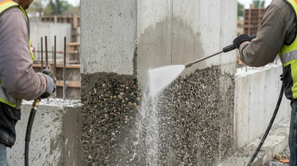
Surface preparation is the most important factor in construction joint performance — more important than joint type or geometry.
Standard preparation sequence:
- Remove all laitance by sandblasting, water blasting (3,000+ PSI), or mechanical scarification
- Expose coarse aggregate across the full joint face
- Clean surface of dust, debris, and standing water
- Apply bonding agent if specified (SBR latex or epoxy bonding agent)
- Place fresh concrete while bonding agent is still tacky
Worked Example: A retaining wall poured in two lifts. First lift cast to 4 feet, cured for 24 hours. Before second lift: construction joint face water-blasted at 3,500 PSI to remove laitance and expose aggregate. Surface wetted to saturated surface dry (SSD) condition. SBR bonding slurry applied immediately before second lift placement. Result: monolithic bond across the construction joint with no visible interface in finished wall face.
Contraction Joints in Slabs on Grade
Contraction joints are a broader category encompassing all planned joint types that induce controlled contraction cracking in slabs on grade — including saw-cut and tooled control joints discussed above, plus formed contraction joints using plastic or metal joint formers inserted into fresh concrete.
Plastic joint formers (Zip-Strip type) are T-shaped or L-shaped plastic strips inserted into fresh concrete immediately after screeding. They remain permanently in the joint, providing both the weakened plane for crack control and a pre-formed reservoir for sealant.
Advantages over saw-cutting:
- No timing risk — installed in fresh concrete
- No saw required — reduces equipment cost
- Permanent joint form — no routing needed before sealing
Limitations:
- Depth limited by strip size — may be inadequate for thick slabs
- Not suitable for industrial floors with heavy traffic (metal wheels can catch the exposed strip edge)
Joint Design by Project Type
Residential Slab Joints
| Element | Joint Type | Spacing | Depth | Notes |
|---|---|---|---|---|
| Patio (4″) | Control | 8–10 ft | 1 inch | Tooled or saw-cut |
| Sidewalk (4″) | Control | 4–5 ft | 1 inch | Match panel to width |
| Driveway (5″) | Control | 10–12 ft | 1.25 inch | Expansion at garage |
| Garage floor (5″) | Control | 10–12 ft | 1.25 inch | Isolation at walls/columns |
Driveway Joint Spacing
Driveways need three joint types working together:
- Control joints at 10–12 foot intervals across the width
- Expansion joint where the driveway meets the garage apron or public sidewalk
- Isolation joint where the driveway abuts the house foundation
Missing any of these three produces predictable cracking at exactly the location the joint should have been.
Industrial Floor Joints
Industrial floors — subject to heavy forklift traffic, point loads, and temperature variation — require the most precise joint design of any flatwork application.
Key specifications:
- Control joint spacing: typically 15–25 times slab thickness (larger panels require fiber reinforcement or post-tensioning)
- Joint edges must be hard and supported — armored joint edges (steel angle or proprietary armor) prevent edge spalling under forklift wheel impact
- Saw-cut timing is critical — early-entry cutting within 2–4 hours of finishing
Joint edge spalling — the progressive chipping of concrete at joint edges — is the most common industrial floor maintenance problem. It is caused by unsupported joint edges deflecting under repeated forklift wheel impact. Armored edges and load transfer dowels prevent it; sealing alone does not.
Foundation Joint Requirements
Foundation concrete joints must accommodate both thermal movement and the structural requirement for waterproofing.
Below-grade foundation walls:
- Construction joints between pours: prepared as described above with roughened surface and dowels
- Waterstop installation: a PVC or rubber waterstop embedded in the construction joint face prevents water infiltration through the joint
- No control joints in walls: wall reinforcement controls cracking; control joints in walls create waterproofing problems
Common Joint Design Mistakes to Avoid
Mistake 1 — Joints too far apart. The single most common error. A 4-inch residential slab with joints at 20-foot spacing will crack between the joints — the concrete has no choice. Use the 2–3× rule strictly: 4-inch slab, maximum 12-foot joint spacing.
Mistake 2 — Joints too shallow. A groove that is only 1/4 inch deep in a 4-inch slab (6% of depth instead of 25%) does not create a meaningful plane of weakness. The slab cracks wherever it wants. Minimum depth is one-quarter of slab thickness — measure and verify, don’t estimate.
Mistake 3 — No expansion joint at fixed boundaries. Omitting expansion joints where slabs meet walls, columns, or other structures is the second most common error. The resulting restraint produces either cracking in the slab or damage to the adjacent structure — both more expensive than the joint filler would have been.
Mistake 4 — Cutting too late. Saw-cut control joints installed after random cracking has already begun are decorative, not functional. The cracks have already formed — cutting a groove next to them does nothing. In hot weather or with high-shrinkage mixes, early-entry cutting within 2–4 hours is essential.
Mistake 5 — Poor construction joint preparation. Smooth, laitance-covered construction joint faces bond poorly — the joint becomes a crack and water infiltration plane rather than a structural connection. Water blasting or sandblasting to expose aggregate is not optional; it is the minimum preparation standard.
Mistake 6 — Wrong joint type for the application. Using a control joint where an isolation joint is needed (at a slab-to-wall boundary) means the joint still bonds the two elements together — the control groove provides no benefit at a fully bonded boundary. Each boundary type requires the correct joint type.
Frequently Asked Questions About Concrete Joints
What are the types of construction joints in concrete?
The main types are control joints (direct shrinkage cracking to planned locations), expansion joints (accommodate thermal expansion at fixed boundaries), isolation joints (separate independent structural elements), construction joints (connect sequential pours), and contraction joints (induce planned cracking in slabs on grade). Each serves a distinct function and is not interchangeable with the others.
What is the difference between a control joint and an expansion joint?
A control joint is a partial-depth groove that creates a plane of weakness where shrinkage cracking is directed — it only accommodates contraction. An expansion joint is a full-depth gap filled with compressible material that accommodates both expansion and contraction. Control joints are used throughout the slab field; expansion joints are used at fixed boundaries and long continuous runs.
How far apart should control joints be in concrete?
For residential slabs, maximum joint spacing equals 2–3 times the slab thickness in feet. A 4-inch slab: joints every 8–12 feet. A 5-inch slab: every 10–15 feet. For industrial floors and pavements, spacing is determined by structural analysis and may be larger with fiber reinforcement or post-tensioning.
How deep should control joints be cut?
Minimum one-quarter of the slab thickness. A 4-inch slab needs joints at least 1 inch deep. A 6-inch slab needs joints at least 1.5 inches deep. Shallower joints frequently fail to control cracking — the slab cracks at full depth adjacent to the shallow groove.
What is an isolation joint in concrete?
An isolation joint is a full-depth separation between concrete elements that will move independently — such as a slab and a wall, or a slab and a column. It allows each element to move freely without transferring stress to the adjacent element. It differs from an expansion joint in that it separates structurally independent elements rather than accommodating movement within a continuous slab.
When is a waterstop required in a construction joint?
Waterstops are required in construction joints in water-retaining structures (tanks, pools, reservoirs), below-grade foundation walls subject to hydrostatic pressure, and any construction joint where water infiltration would cause damage or structural concern. A waterstop is a continuous PVC or rubber strip embedded across the joint face — it creates a physical barrier to water migration through the joint.
What causes construction joint failure?
The most common causes are inadequate surface preparation (laitance not removed, surface contaminated), insufficient bond area, missing mechanical connectors (dowels or keys) where load transfer is required, and fresh concrete placed against dry, dusty, or frozen joint faces. Proper preparation — clean, roughened, SSD surface with bonding agent — prevents most construction joint failures.
Do all concrete slabs need expansion joints?
All exterior concrete slabs need expansion joints wherever they meet fixed structures — walls, columns, curbs, and building foundations. Interior slabs in temperature-controlled environments may not need expansion joints if temperature variation is minimal. Long continuous exterior runs (over 50 feet) need expansion joints regardless of whether they meet fixed structures.
Conclusion
Joints are not optional details in concrete construction — they are the mechanism by which concrete accommodates the movement that is physically inevitable. Every concrete element shrinks, expands, and settles to some degree. The question is not whether movement will occur but whether it occurs at planned joints or at unplanned cracks. Control joint spacing, depth, timing, and type selection are the decisions that answer that question. Get them right in the design and construction phase — fixing uncontrolled cracking after the fact costs far more than correct joint installation would have. For new concrete pours requiring accurate volume calculations, use the ConcreteCal concrete calculator before ordering materials.